TestOil introduces an Improved Technology For Analyzing Industrial Filters

FILTER DEBRIS ANALYSIS
TestOil has updated their Filter Debris Analysis testing process. The improvements have significantly increased the laboratory’s ability to identify wearing machine components which provide improved diagnostic and prognostic information about impending failures.
Filter Debris Analysis is a systematic process developed to wash and analyze industrial size filters. TestOil has made substantial changes to all aspects of this testing procedure including the fabrication of a new washing instrument, a completely redesigned washing method, an enhanced testing process, and a revamped comprehensive report.
“Our customers depend on us to provide the most reliable oil analysis testing data to ensure machine performance and reduce risks of failure,” said Eric Ambrose, Director of Technical Operations, TestOil. “The Filter Debris Analysis upgrade expands on that commitment as well as staying on top of the latest technological developments.”
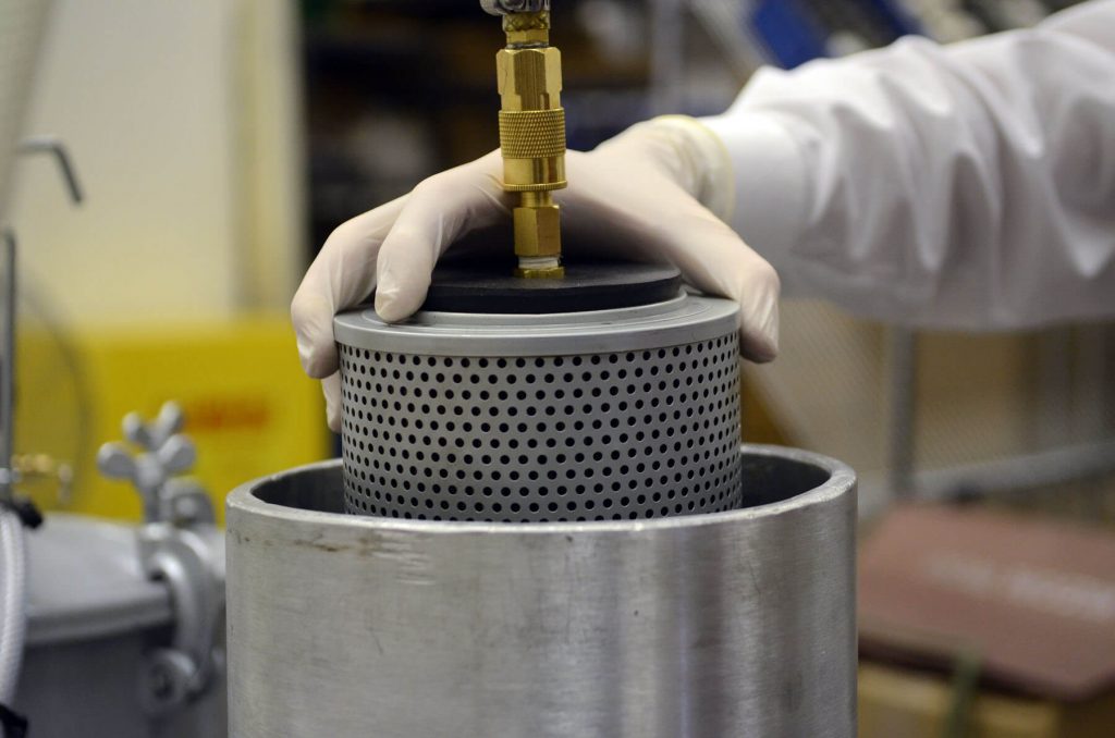
The first step in the new testing process, and one of the most significant changes, includes a new filter washing instrument that was designed by Eric Ambrose. “The modular design can accommodate more irregular filters such as large-sized filters and bag or sock filters,” explains Ambrose. “During this new process, filters are now washed using solvent and compressed air, and there are no electrical components, which allows for the use of flammable solvents.”
In addition, attachments are connected to the filter in order to seal them and perform a true “back-flush” by using solvent and compressed air. The attachments are also capable of performing a more repeatable wash of the filter and achieve a better representation of debris caught within the media for analysis.
Once the debris stream is collected from the washing unit it is then moved to the lab for analysis. TestOil now performs an optical particle count on the debris stream collected from the filter. The purpose of the particle count is to provide secondary particle quantification trending supplementing the debris patch. The particle counter is able to detect a wide range of particles. This range includes particles as small as 5 microns and particles as large as 68 microns.
The methodology behind the membrane patch is new as well. Membrane patches are created and gravimetrically weighed to collect debris, to calculate the total amount of debris collected from the filter, and to trend data. A 30-micron patch and 5-micron patch are made and analyzed to differentiate severe wear and normal wear, respectively. The 30-micron patch collects larger particles while the 5-micron patch collects smaller particles. In the apparatus, the 30-micron patch sits above the 5-micron patch allowing smaller particles to pass through.
Once the debris has been gravimetrically weighed and collected on both the 5 and 30-micron patches, analysts view the 30-micron patch under a microscope. A representative magnified image of the wear particles is then captured. The image of the wear particles is found on the report.
Lastly, the 5 micron and 30-micron patches are analyzed with XRF Spectroscopy. The XRF can determine the range of elements present as well as their proportions within the sample.
Once testing is complete the data is assembled in a comprehensive test report. Analysts review the data and conclude an appropriate determination of the machine’s condition. In addition, the report displays images of the filter and patches, microscopic views of the patches, and pie charts displaying elemental data.


